The Hi-Fix system was engineered to fulfil a number of roles, varying form temporary deployments to fixed chains. To enable this, the equipment comprised a series of units each built on a 19-inch chassis 4U high (usually) and housed in a light alloy military-style Creeth transit case. The cases could be fastened together to form a rack, or be free standing.
System Description
Hi-Fix System Description
The equipment used both miniature valves and transistors in its circuitry. The valves were of the type popularly referred to as 'pencil valves', on a miniature wire-ended 8-pin base. The transistors were a mix of silicon and germanium devices. Within each unit, a transistor invertor supplied the valve HT, and most of the other voltages required. The DC supply to all units was 24V positive earth, intended to be supplied from lead-acid batteries. A tap on the battery at 12V also required by the receiver.
The Hi-Fix system comprised the following main components. The links in the table below will take you to a full description of the unit.
| Item | Decca Type Number | Comments |
|---|---|---|
| Hi-Fix Master Drive Unit | 9216 | Used on Master Station |
| Low Power Transmitter | 9371 | 10W Output, used on Master and Slave Stations |
| Medium Power Transmitter | 9362 | 40W Output, used on Long Range and Permanent Stations |
| Hi-Fix Receiver | 9217/III | Used for User Receiver and on Slave Stations |
| Blower Unit | 9217/BM | Cooling blower, provides base stand for receiver |
| Distribution Unit (DU) | 9218 | Provides control and monitoring of power supplies |
| Blower and synchro supply unit | 9369 | Provides power for synchros in receiver for remote displays and plotter, incorporates blower. |
| Track Plotter | 9232 | Provides a continuous plot of track |
The HiFix system required 3 transmitter stations. One of these, the Master, was located centrally between two slaves, and at the intersection of the baseline from Master to Slave 1, and Master and Slave 2. The sites transmitted in sequence on the same RF frequency, as shown in the diagram below:
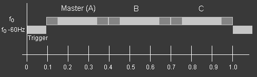
The main frequency (referred to as the 'pattern frequency') could be in the range 1700 to 2000 kHz, but any one chain and its associated user receiver would be set up to operate on one of 4 channels within a 25 kHz switching bandwidth. The three sites all radiated a 200mS pulse within a 300mS 'slot', which allows for a 'guard time' to allow for the operation of the various switching circuits. In addition to the main pulse on the pattern frequency, the master station also transmitted a trigger pulse on the 'signalling frequency'- a frequency 60Hz lower than the nominal pattern frequency.
Click play on the player to listen to a simulation of a Hi-Fix chain in operation.